Sensors and Actuators are the bread and butter of Home Automation. Why? Becuase when you add them to the equation, you can automate behaviors based on a changing environment. Turning on your smart bulbs when a light sensor detects that it is dark for example. The problem here is that commercial sensors are very expensive and rather limited in functionality. There is good news though, we are DIY people! Today I want to show you how to build your very own DIY Home Automation Sensors.
I am very excited about this post because the framework that I am going to present today took my Home Automation Project to a whole new level. I am talking about MySensors. If you have not checked the website you definitely should, they have awesome projects.
So…What will you have at the end of this tutorial?
When you finish the tutorial you will have 2 wireless sensors, temperature and Humidity, feeding values into your Home Automation Controller, OpenHab. Once you build the first sensor, adding new ones (Light, Door/Window, Motion…) is extremely cheap and quick. The tutorial takes between 1 and 2 hours.
If you are starting with Arduino you should check this book, it will help you getting up and running.
What is MySensors?
Using their own words…
MySensors is an open source hardware and software community focusing on do-it-yourself home automation and Internet of Things.
MySensors is a framework that uses very well known components in the DIY world like Arduino, Raspberry Pi, ESP8266 and NRF24L01 to create DIY Home Automation Sensors and Actuators.
You might be wondering how is this different from connecting cheap sensors to an Arduino board following a tutorial on the Internet.
While experimenting with these components is fun a great learning experience, when it comes to integrating those sensors and actuators into your Smart Home, there are a number of things that you need to worry about. Just to mention a few of them…communications, security, reliability…
If you want to have a seamless integration, you will have to spend time designing everything from scratch yourself.
Here is where MySensors comes to the rescue. The library takes care of the tedious side that you need to implement on every single node of the network and leaves you with the fun part, creating new sensors in no time and at a very low-cost.
Anything else?
Yes, It uses MQTT so you can integrate every sensor that you create with pretty much every Home Automation Controller out there.
DIY Home Automation Sensors with MySensors: Architecture
The best way to get an understanding of the architecture is by going through an example.
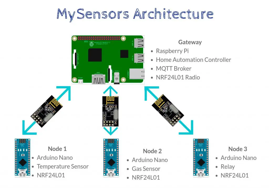
MySensors Gateway
Although the Raspberry Pi isn’t the most common device to implement a MySensors Gateway (most people use Arduino), I have decided to go for it.
Why? Mainly two reasons:
- If you are building an Open Source Home Automation Project, chances are that you already have a Raspberry Pi as a controller. You can save a few bucks right there.
- This architecture provides an all-in-one solution. Home Automation Controller and RF gateway.
So…What is the gateway?
The gateway will be the brains of the operation. These are the main tasks it carries out:
- It sends and receives messages from/to the nodes using the radio (NRF24L01).
- It publishes messages coming from the nodes into a topic in the MQTT Broker.
- The Home Automation Controller (OpenHab, Home Assistant, Domoticz..), also installed in the same Raspberry Pi, uses the MQTT broker to consume and publish messages to and from the nodes.
The gateway, in essence, holds everything together to provide a seamless experience.
MySensors Nodes (Sensors and Actuators)
The nodes are the actual DIY Home Automation Sensors and Actuators.
Sensors provide you with valuable information about your house, like the temperature in every room. Actuators, on the other hand, wait for commands from the controller. You could, for example, control a relay that switches on and off a lamp.
Components
Before you get down to business, it is useful to get familiar with the components that you will be using, in case you are not already.
Raspberry Pi GPIO Pins
Among all the things a Raspberry Pi can do, It also gives you the possibility to interact directly with electronic components like sensors or actuators. We could dedicate several posts to this topic but today I am only focusing on creating a MySensors gateway with it. If you want to know more about the GPIO capabilities of the Raspberry Pi check this link.
OK…so You see 40 pins coming out of the Raspy. What are they?
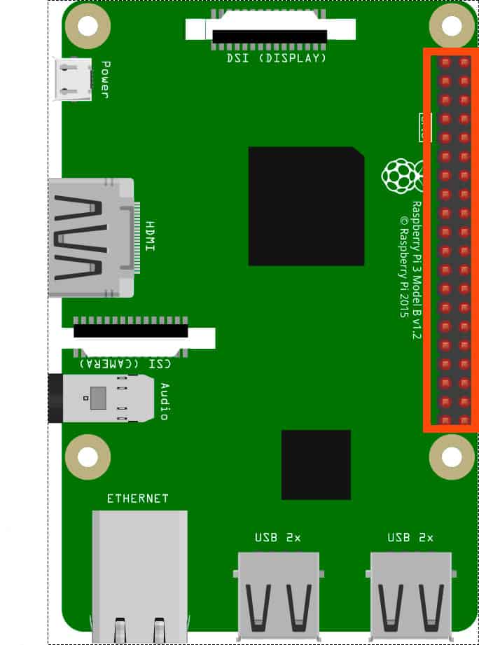
There are basically five types of pins on the Raspberry Pi.
- 5V Power: VCC pin that delivers 5V.
- 3.3V POWER: VCC pin that delivers 3.3V.
- GND: Ground pin for 5V and 3.3V.
- GPIO Pins: These are Digital I/O pins that you can use to control or get information from electronic components.
You don’t need to be familiar with all of them, but just as a reference, here you have the full layout for the 40 pins.
| ID | PIN | ID | PIN |
| 1 | 3.3V POWER | 2 | 5V POWER |
| 3 | GPIO 2 | 4 | 5V POWER |
| 5 | GPIO 3 | 6 | GND |
| 7 | GPIO 4 | 8 | UART0 TX |
| 9 | GND | 10 | UART0 RX |
| 11 | GPIO 17 | 12 | GPIO 18 |
| 13 | GPIO 27 | 14 | GND |
| 15 | GPIO 22 | 16 | GPIO 23 |
| 17 | 3.3V POWER | 18 | GPIO 24 |
| 19 | GPIO 10 | 20 | GND |
| 21 | GPIO 9 | 22 | GPIO 25 |
| 23 | GPIO 11 | 24 | GPIO 8 |
| 25 | GND | 26 | GPIO 7 |
| 27 | Reserved | 28 | Reserved |
| 29 | GPIO 5 | 30 | GND |
| 31 | GPIO 6 | 32 | GPIO 12 |
| 33 | GPIO 13 | 34 | GND |
| 35 | GPIO 19 | 36 | GPIO 16 |
| 37 | GPIO 26 | 38 | GPIO 20 |
| 39 | GND | 40 | GPIO 21 |
NRF24L01

The NRF24L01 is a very low-cost RF chip that works at 2.4Ghz. The communication between the gateway (your Raspberry Pi) and the sensors and actuators (tons of Arduinos all over the place..) will be done using the NRF24L01 chip. Each one of the nodes of your network, including the gateway, will have one of this.
The chip has a decent range. You are looking at about 250 to 300 ft. There are ways to extend the range of your sensors but I will reserve that for a future post.
Arduino
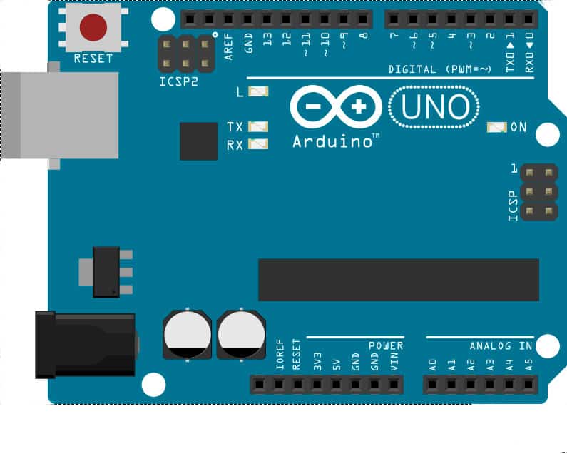
I will not take much of your time with this since there is information about Arduino pretty much on every corner of the internet. If you have never played with it before, you should check their Getting Started Page. You will be up to speed in no time.
So…Finally! Let’s build something!
As you can see, the DIY Home Automation Sensors tutorial has 3 parts. It might appear daunting at first but I can assure it is very simple. The first 2 parts will walk you through the network setup step by step, which you only have to do once. After that, adding new nodes to the network is quick and simple.
DIY Home Automation Sensors with MySensors: Practical Example
Bill of Materials
| Units | Description |
| 2 | NRF24L01+ 2.4GHz Wireless RF |
| 1 | Arduino Nano V3 |
| 1 | Jumper Cables |
| 1 | DHT22 Temperature and Humidity Sensor |
| 1 | Raspberry Pi Kit |
I suggest you buy a few extra NRF24L01 and maybe Arduinos. As soon as you get your first sensor up and running you will want to make more of them 🙂
Step 1: Install an MQTT Broker in OpenHab (Estimated time ~15 Minutes)
The first step is to get an MQTT Broker up and running in your Home Automation controller. I know this is a bit painful but you will only have to do this once. Click on the image to go to the step by step tutorial.
Step 2: Build the MySensors Gateway using a Raspberry Pi (Estimated time ~25 Minutes)
The second step will get you geared up with the MySensors Gateway. Like the first part, you will only have to do this for the first node.
Step 3: Build your First Sensor with DHT22 and Arduino Nano (Estimated time ~35 Minutes)
The very last step is wiring the components for the actual DIY Home Automation Sensors. Click on the image to follow the tutorial on how to create your first sensor.
There you go, your network of DIY Home Automation Sensors is up and running. I hope you found this useful. If you find any issue while going through the tutorial please post some comments. I will do my best to help you.







Can I use a ESP8266 instead? I dont want to use a raspi simce I already use my server and a docker.
Hi Angel,
You can definitely use the ESP (https://www.mysensors.org/build/esp8266_gateway) or even a plain arduino. I actually started using a raspberry pi and later moved the gateway to an Arduino so you have many options and you can even pivot later.
Such a good blog post (like all the others I have read on this site).
Great attention to detail which helps less experienced Electronics DIYers like myself.
Keep up the great work!